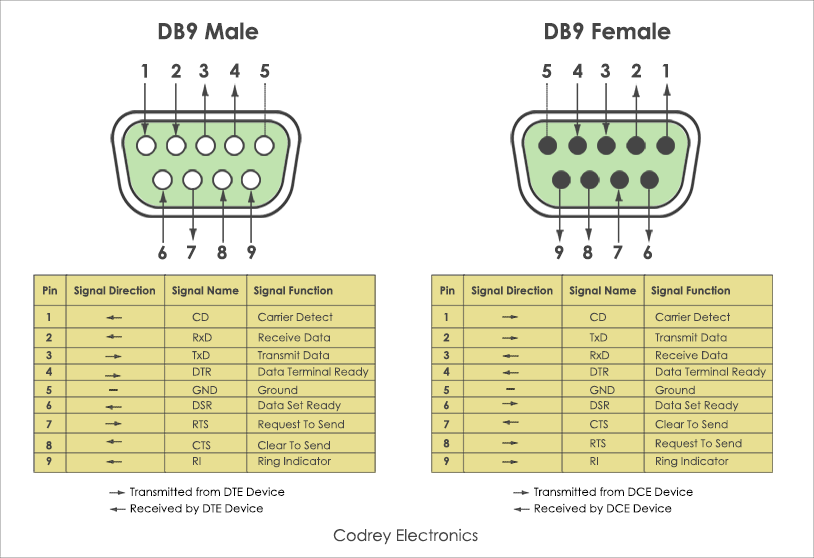
Pinout of Serial Printer (9-25) Epson cable and layout of 9 pin D-SUB female connector and 25 pin D-SUB male connectorFor most of models Epson printers.

Toward the end, there’s a diagram of the pinouts for the cable. It’s a null modem cable without flow control. It uses 3 wires – GND, TxD, RxD.
Db9 Rs232 Cable Pinout
Instead of using a traditional serial cable – aka, a “null modem cable”, we use these adapters. They come in both DB9 to RJ11 and DB9 to RJ45 forms. I got the latter, but either one works. Here’s what they look like: (pics from ) They appear to have putty colored ones. I got some cool looking black ones from Fry’s, but now regret it – you can’t write in black Sharpie on black plastic:(. You construct them by pushing the gold “holes” into the holes, which are numbered 1 to 9. In between these, you use phone cord, or in my case, some Cat-3 and RJ11 modular plugs.
It’s easiest to use the plugs with only enough room for 4 wires, as that’s all you need. The reason for using a rolled cable or phone cord is that it’s totally standard. If the equipment needs to be rearranged, and the cable is lost, it’s likely someone will recall that it looked like phone cord, and use phone cords to re-establish the connection.
The phone cord will work. What I did was clip the white wires, leaving the colored ones. On one end, they’re arranged in order, and at the other end, in reverse order. The actual order doesn’t matter, but you can use Green-Blue-Orange-Brown (which recalls the EIA standard), and Brown-Orange-Blue-Green at the other end.
The RJ45 version should conform to this, as the RJ11 plug will also work with telephone cords that have four conductors. The RJ11 to DB9 is: 1 – NC 2 – RD 3 – GND 4 – GND 5 – TD 6 – NC I don’t have the colors for the wires coming from the RJ11, unfortunately.
RJ45 just adds one conductor on each side, so the numbers should be: 1 – NC 2 – NC 3 – RD 4 – GND 5 – GND 6 – TD 7 – NC 8 – NC And on the DB9 side, using the standard colors: 1 – Blue 2 – Orange 3 – Black – 2 4 – Red – 5 5 – Green – 5 6 – Yellow – 3 7 – Brown 8 – White Both red and green wires need to be grounded to pin 5. If you don’t, you won’t get a signal in both directions. But you can’t put two pins into one hole.
That’s a problem, and the solution is to solder the green wire onto the red one. Cut the green wire just below the “hole” – the gold thing that gets shoved into the hole. Strip around 1/16th of an inch of insulation with your thumbnail.

Take a toothpick and use it to put a tiny dab of flux on the wires, and then a tiny dab onto the red wire’s “hole” just north of where it gets crimped. This flux matters a LOT, and this won’t work without it. (If you don’t use flux, get some. It’s worth it.) Heat up your iron – a 15 watt one is fine.
Melt a tiny bit of solder on the tip, and then tin the stripped wire. The insulation will melt back a bit. Now, put some solder onto the red wire’s connector, right on the flux. Pull it away once it’s flowed. Now, using small pliers, hold the tinned wire and the tinned connector together, and heat them with the iron so they stick together. The trick is to solder them tight without leaving a big blob of solder.
If you have a tiny peak of solder, that’s OK. You can push that down with the pliers.
Epson Serial Cable Pinout
Now, push this red wire into the hole for pin 5. You might need to push a bit with the pliers. Once it’s done, I like to clip the unconnected wires, so it’s a neat install. Other folks just push them inside the shell.
You can close up the shell by twisting the DB9 a couple times so the wires tend to coil up into the shell. If you put the “hole” into the wrong position, you can push it out with a paper clip. You take a small paper clip and straighten out the end. Put the wire into the hole (as if it’s a male pin), and then, using pliers, hold the wire tight, and push the DB9 firmly toward the wire. Don’t jam it – just hold the DB9 tight, and push, firmly. You’ll feel a “click” as the connector is released.
Db9 Cable
RJ-45 to DB-9 Serial Port Adapter Pinout Information The console port is an RS-232 serial interface that uses an RJ-45 connector to connect to a management device such as a PC or a laptop. If your laptop or PC does not have a DB-9 male connector pin and you want to connect your laptop or PC to the device, use a combination of the RJ-45 to DB-9 female adapter along with a USB to DB-9 male adapter. Provides the pinout information for the RJ-45 to DB-9 serial port adapter. Table 1: RJ-45 to DB-9 Serial Port Adapter Pinout Information RJ-45 Pin Signal DB-9 Pin Signal 1 RTS 8 CTS 2 DTR 6 DSR 3 TXD 2 RXD 4 GND 5 GND 6 RXD 3 TXD 7 DSR 4 DTR 8 CTS 7 RTS.
